Torque from inside the engine
Electromagnetic assistance is coupled to the reciprocating mechanism rather than a separately mounted traction motor in the proposed configuration.
ODD Research & Development · Proposed propulsion technology
Combustion and electromagnetic force, coordinated within the same engine cylinder.
The Hybrid Bullet Engine (HBE) explores whether a hybrid electrical system can deliver controlled force directly to reciprocating pistons—and potentially recover energy during selected operating conditions. This is an engineering-stage invention, not a demonstrated production engine.
THE INVESTMENT THESIS / A DIFFERENT HYBRID ARCHITECTURE
The Hybrid Bullet Engine proposes an unconventional route to hybrid assistance: precisely timed electromagnetic force acts on the same piston already driving the crankshaft. Combustion remains essential. Electrical energy comes from a hybrid battery or pulse-storage system—not from nowhere.
Electromagnetic assistance is coupled to the reciprocating mechanism rather than a separately mounted traction motor in the proposed configuration.
A controller would time stator activation to useful crank angles, subject to battery energy, coil heating and available field strength.
Measure real force, input energy and thermal behavior on an instrumented rig, then decide whether full-engine development is justified.
THE CONCEPT IN FOUR STEPS
The electric system does not replace combustion. It supplies energy for an additional controlled force during selected piston travel, with the crankshaft collecting the resulting mechanical work.
Battery and optional pulse-storage hardware provide electrical power.
Control electronics schedule field excitation relative to piston position.
Stationary windings interact with the proposed piston magnetic member.
Additional axial force may increase useful mechanical work after losses.
The engineering advantage is a hypothesis, not a demonstrated result: HBE could offer a useful packaging or torque-control alternative in certain engines, but it must be compared against conventional hybrid-motor solutions for efficiency, mass, durability and cost.
01 / Animated operating principle
External electrical energy drives stationary coils. The synchronized field is intended to add force to the moving piston, increasing crankshaft torque after losses.
Illustration is conceptual. It does not simulate measured fields, piston kinematics, timing or actual engine performance.
02 / Engineering figure explorer
Explore the original technical illustrations, from the V6 stator-sleeve system to the removable piston cooling cartridge. Select a figure to read its description, or enlarge the original image.
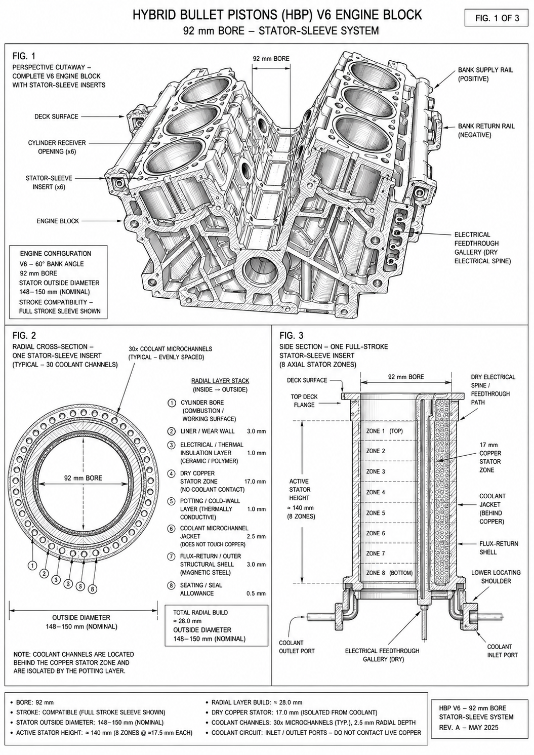
Figure 01
Six stationary electromagnetic sleeves surround the piston bores, with eight proposed axial stator zones per cylinder.
Design illustration; dimensions and packaging require validation.
03 / Potential mechanical output
The concept uses an existing reciprocating engine mechanism as the mechanical interface for electromagnetic assistance. That can avoid a separate traction motor in the conceptual architecture, but it does not eliminate the electrical energy needed to produce additional torque.
Equivalent to 37.29 kW of modeled mechanical assist. The electromagnetic system would need approximately 7.56 kN of mean useful axial piston force during the assumed assist window.
Equivalent to 55.93 kW of modeled mechanical assist, requiring approximately 11.35 kN of mean useful piston force over the same 15°–55° window.
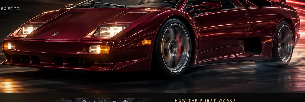
What this means: These numbers describe additional average crankshaft torque if the required force is achieved. They are not a measured power curve, a 0–60 mph prediction, or proof that the electromagnetic hardware can supply the field. The 120+ hp image below illustrates the separate, unverified burst target.
SPORT MODE / CONCEPT VISUALIZATION
Concept artwork illustrating the proposed short-duration electromagnetic assist layered on top of combustion power.
Engineering model versus burst target: The table below uses the revised 5,000 RPM V6 performance curve from the project’s Net Power Validation study. The 50 hp and 75 hp cases are calculated model points, not measured prototype output. The 120+ hp burst remains a proposed short-duration target, subject to electrical, thermal and mechanical validation.
| Revised V6 loss assumptions · 5,000 RPM | 50 hp assist | 75 hp assist |
|---|---|---|
| Electrical input | 53.43 kW | 79.97 kW |
| Useful crankshaft output | 37.29 kW | 55.93 kW |
| Modeled input-to-output efficiency | 69.8% | 69.9% |
| Modeled power losses | 16.15 kW | 24.04 kW |
Engineering audit · Geometry → Magnetic field → Crankshaft power
Instead of inferring magnetic force from a desired horsepower number, this assessment checks the V6 crank-slider geometry and then calculates the air-gap field conditions needed to produce that force. The calculated force requirements are exact for the stated mechanical assumptions; the magnetic-field scenarios are conditional screening estimates, not demonstrated stator output.
| Engine and cycle | Four-stroke V6; one assisted power stroke per cylinder per 720° |
| Speed and crank-angle window | 5,000 RPM; 15°–55° after top dead center |
| Stroke / crank radius / rod length | 82.7 mm / 41.35 mm / 150 mm |
| Magnetic reference from piston draft | 84 mm mean diameter; 80 mm translator length; 78.7% effective coverage |
| Reference active surface area | 0.01661 m² ≈ 0.0166 m² |
Crank radius r = 41.35 mm; connecting rod L = 150 mm. From 15° to 55° ATDC, Δx = 19.71577 mm.
Four-stroke V6 at 5,000 RPM: 250 assisted events/s. The 50 hp and 75 hp cases require 7,565 N and 11,347 N mean useful thrust, respectively.
| Computed requirement · 5,000 RPM | 50 hp | 75 hp |
|---|---|---|
| Additional crankshaft output | 37.285 kW | 55.927 kW |
| Crankshaft work per assisted event | 149.140 J | 223.710 J |
| Mean positive axial thrust in the active window | 7,565 N | 11,347 N |
| Required reference-surface magnetic shear | 456 kPa | 684 kPa |
| Average added crankshaft torque | 71.21 N·m | 106.81 N·m |
Interpretation: These are mean force requirements during the selected 40° window, not instantaneous peak forces and not measured electromagnetic force. A nonuniform force profile generally requires peak thrust above the tabulated mean.
Bₙ and Bₜ are air-gap field components; kτ is an assumed utilization factor. This is a screening approximation, not a field solution.
84 mm mean diameter × 80 mm active length × 78.7% coverage. The coverage value comes from the proposed geometry.
Explicit, unverified screening assumptions: Bn = 1.0 T; kτ = 0.70; Aeff = 0.0166 m². Assume these values apply over the entire 15°–55° interval, with approximately uniform positive axial thrust, full usable overlap, and no additional mechanical losses. They are not FEA or prototype results.
| Assumed tangential air-gap field | Calculated mean thrust | Conditional crank output |
|---|---|---|
| 0.3 T | 2.77 kN | 18.3 hp |
| 0.5 T | 4.62 kN | 30.6 hp |
| 0.8 T | 7.40 kN | 48.9 hp |
| 1.0 T | 9.25 kN | 61.1 hp |
Assuming Bₙ = 1.00 T and kτ = 0.70, the 50 hp and 75 hp cases require Bₜ ≈ 0.817 T and 1.226 T. These are requirements, not simulated fields.
| Air-gap requirement under screen assumptions | 50 hp | 75 hp |
|---|---|---|
| Normal field Bn (assumed) | 1.00 T | 1.00 T |
| Required tangential field Bt | 0.817 T | 1.226 T |
| Requirement status | Demanding; unverified | More demanding; unverified |
Feasibility warning: Requiring ~1.23 T of tangential field alongside 1.0 T normal field, with 70% utilization over the full power window, is an aggressive magnetic-circuit requirement. Strong saturation, leakage, slotting, varying overlap, back-EMF, and temperature can reduce actual force. Neither 50 hp nor 75 hp is established without an electromagnetic force-versus-current-and-position solution.
The project’s Net Power Validation revised table lists 53.43 kW electrical input for 50 hp and 79.97 kW for 75 hp, implying ~69.8–69.9% conversion. These values are source-document assumptions, not derived from the shear equation. Actual input and efficiency require winding turns, drive waveforms, phase currents, hot resistance, back-EMF, eddy-current loss, inverter data and measured thrust.
The electrical-input figures come from a separate preliminary loss model; the electromagnetic force equation does not predict their efficiency.
Engineering sources: HBE Part I — Hybrid Bullet Piston, Professional Counsel-Review Draft, §§10.6, 11.1–11.3 (magnetic shear, 84 mm / 80 mm translator reference, 0.0166 m² area, and 150 mm connecting rod); Net Power Validation, “Old vs new curve table at 5000 rpm.” This is a screening comparison between a specific magnetic-translator embodiment and the V6 power targets. The separate magnet-free induction architecture needs its own validated induction/thrust-slip model. No prototype testing or electromagnetic finite-element analysis is claimed.
The revised model predicts roughly 70% electrical-to-crankshaft conversion for these two operating points. Battery charging, inverter losses, generation losses, added engine mass, cooling demand, and vehicle-level efficiency must still be evaluated experimentally. These numbers are not claims of free energy or proven fuel-economy improvements.
Supply electrical energy to the stator during selected crank-angle windows to create useful piston force.
Investigate generator operation when mechanical energy is available, recognizing that energy extraction adds resisting torque.
Use a controller to select operating points based on torque demand, electrical losses, temperature and available stored energy.
The first investment should buy an answer to that question—not a promise of an instant production Lamborghini or a certified 120 hp burst.
04 / Proof before production
A prototype can demonstrate whether the core electromagnetic and cooling principles work, reveal manufacturing constraints and provide measured performance. One successful prototype alone cannot prove mass manufacturability. That requires repeatable manufacturing processes, durability data, cost models, quality control and automotive integration.
Compare magnetic and induction variants; validate force, heat, stress and electrical requirements.
Measure thrust, input power, winding temperature, coolant pressure drop and seal integrity.
Measure incremental crankshaft torque, net efficiency, thermal behavior and durability.
Test repeatability, cost, serviceability, supply chain and vehicle-level benefits.
Prototype pass/fail criteria should include net mechanical output versus electrical input, continuous thermal stability, mechanical fatigue, repeatability, manufacturable tolerances and cost targets. No such tests are represented as completed.
THE INDUSTRIAL DECISION
The proposed development path is deliberately gated. Each phase produces evidence that can support continuation, redesign, licensing discussions or termination before larger capital commitments.
Deliverables: electromagnetic FEA, current and flux maps, mechanical stress analysis, and a bench rig that directly measures force versus position.
Deliverables: coolant-flow and winding-temperature data, piston-cycle testing, electrical-loss measurements and component life evidence.
Deliverables: independent dyno measurements, packaging/cost analysis, serviceability findings and a direct comparison with a conventional hybrid solution.
Initial capital would be scoped to instrumentation, simulation, prototype fabrication and independent testing. Funding amount, equity and licensing terms are not predetermined on this page.
INVESTOR QUESTIONS / ANSWERED UP FRONT
From electrical energy delivered by a hybrid battery or pulse-storage system through an inverter and stator windings. The proposed field creates mechanical assist at the piston. Energy recovery, if implemented, would impose resisting torque and cannot create net energy.
No. The 50 and 75 hp values are modeled mechanical outputs, tied to geometry and force requirements. The 65 hp efficiency region and 120+ hp burst are proposed design targets. The page does not represent any of those outputs as dyno-tested results.
The design exploration combines crank-synchronized electromagnetic piston assist, a segmented piston magnetic member, a cooled stator and active piston cooling. Whether any specific claim is patentable, filed or enforceable requires a separate documented IP review; technical drawings alone do not establish patent protection.
That is not yet established. A production hybrid motor is the appropriate benchmark. The project must show a compelling vehicle-level advantage in torque delivery, packaging, cost, integration or another measurable metric after accounting for losses, mass, thermal demands and reliability.
A properly instrumented rig can demonstrate electromagnetic thrust, input power, thermal behavior and repeatability. An engine dyno can then test net crankshaft assist. Neither result alone demonstrates mass manufacturability; that requires durability, cost, repeatability and supply-chain evidence.
05 / Industrial collaboration
The next milestone is an independently measurable electromagnetic piston-assist demonstrator—not a marketing horsepower claim. Industrial partners can explore technical collaboration, prototype sponsorship, licensing or potential equity arrangements through the shared investment page.